Consulting
Consulting and manufacturing including planning and design for optics and telescope
| Grinding process | Planning grinding condition optimized for optical material ,quartz, low expansion material, Clearceram. Supporting techniques of optics under grinding. Suitable condition and corrective process considering grinding pressure. |
|---|---|
| Polishing Process | Flash polishing for improvement of reflectivity of the ground surface. Corrective polishing with figure error map. Polishing of free of edge roll down. Optimization of polishing tool. |
| Metrology | Fizeau interferometer. CGH interferometer for off-axis aspheric. High precision mechanical metrology for free form surface. |
| Data stitching | Technology for extension of measurement range by data stitching. |
| Opto-mechanics | Optimization of support point configuration under actual usage of optical elements. Optical evaluation and design of support structure. |
Griding Process
Grinding of one micron accuracy can be realized.
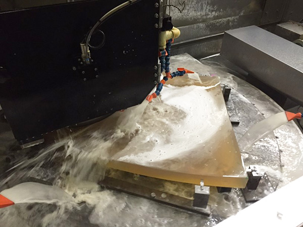
Kinematic support grinding
In general, grinding process proceed many times of small amount cut for achieving the target accuracy. If there is friction and slip exist in the supporting structure of optics, repeatability of cutting process will be degenerate. We achieve high precise repeatability by removing friction and sleeve in the structure.
Configuration of supporting points optimized by finite element method
It is very important to hold the work (generally glass material) under process. It is highly difficult to grind work correctly by conventional supporting method due to footprint from inconsistency between the back surface of the work and supporting table. We achieved a polishing condition close to the actual usage on the telescope by following.
- Basing on the manner of kinematic support.
- Searching the configuration of support points to minimize the deformation of the work by analysis of finite element method.
- Employing a jig to compensate the deformation by own weight.
Selection of suitable grinding stone
It is important to select the grinding stone meeting to your purpose. We execute grinding process by optimized stone with considering removing rate, target accuracy, and roughness.
High precision grinding and prediction of deformation by grinding pressure by the kinematic support
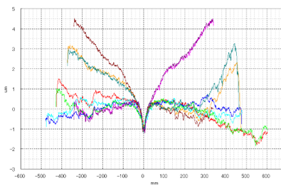
Figure error of cross section without corrective grinding (1div = 1 um)

Figure error of cross section with corrective grinding
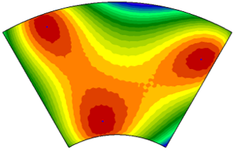
predicted map of deformation by grinding pressure
P-V = 5 um
Filled circle shows fixed point
Polishing Process
The processing improves surface roughness and figure error of ground surface to an optical surface by corrective polishing.
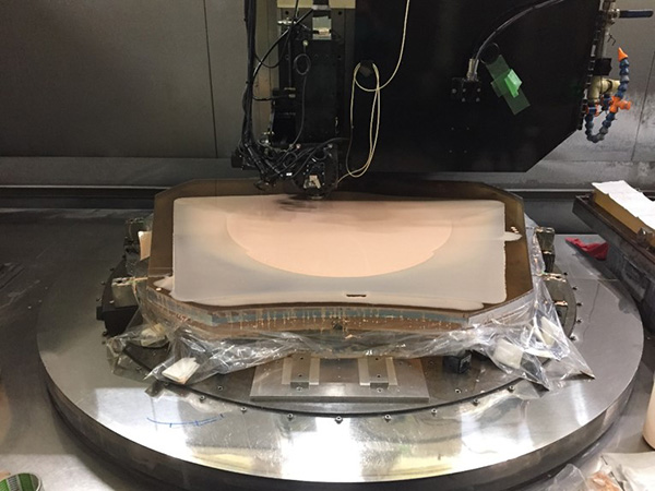
Effective removing of grinding footprint
Characteristic footprint of grinding stone (tool-mark) appears on the work by harmonic motion between the speed of stone traveling motion and rotation. It took long time to remove the tool mark by conventional polishing so far. We solve this problem by our polishing techniques.
Optimized polishing by using convolution method
Corrective polishing is executed by control the dwell time of the polishing tool on the work. We can correct the figure error quickly by calculating the dwell time with convolution of the figure error map and the material removal shape of the polishing tool.
No edge effect by water jet cut
Cutting off the peripheral material by water jet after polishing, no edge effect is realized.
Metrology
Metrology for off-axis aspheric mirror by CGH interferometer
- Available to test an off-axis mirror
- High contrast interferogram
- Robustness against vibration and air turbulence
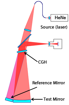
absolute accuracy : 80 nm p-v, 15 nm rms
repeatability : 70 nm p-v, 10 nm rms
lateral resolution : 2.8 mm
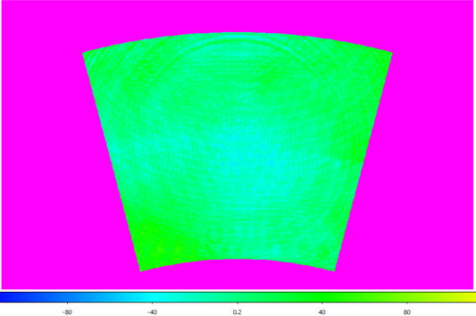
Result
Dragged three-probe method
Obtaining cross section by integrating local curvature measured by three probes.
Free-form measurement without standard
On-machine measurement
Robustness against the environment
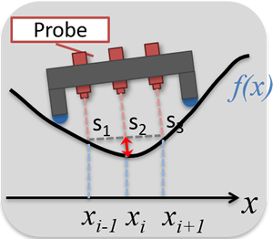
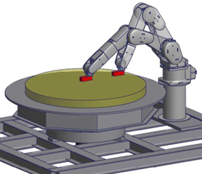
A processing machine can be extended to a metrology system
small
Simple and inexpensive
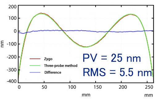
Comparison of a result obtained by Zygo inteferometer
green curve : cross-section measured by three-probe method
red curve : result measured by Zygo interferometer
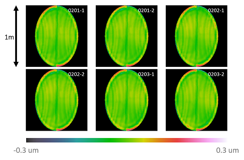
Repeatability of 3 probe method
Repeatability of 10nm(RMS)for 1m size flat mirror
Opto-mechanics
Large optics easily deform due to difference of thermal coefficient between the optics and support structure and own weight. To avoid this problem, the optical element should be support stiffly without over constraint. The technique is opto-mechanics. Kinematic support (no friction and sleeve motion inside structure) is very important to position accurately an optics. We have techniques to position one meter size optics with accuracy of 50 nm RMS on a telescope.
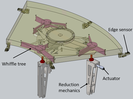
Support structure of segmented mirror of SEIMEI
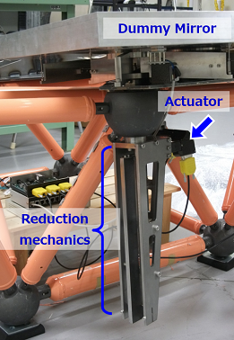
Nano-level positioning accuracy for 80kg mirror is realized by conventional stepping motor with the flexure reduction mechanics.
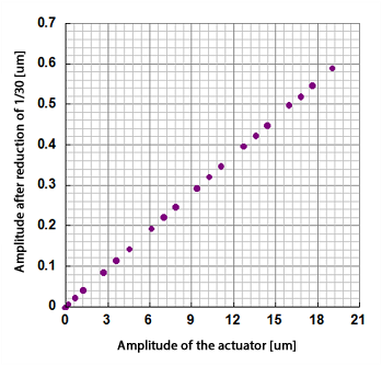
Zero lost motion of the reduction mechanics